認識開發板(以Ameba為例)
-
待完成
-
閃燈
【主題】讓藍燈閃爍
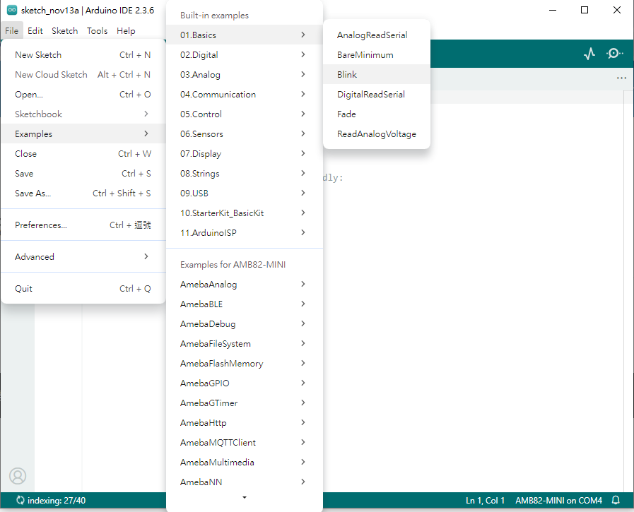
從Arduino內建的範例中,開啟程式碼,如下圖。
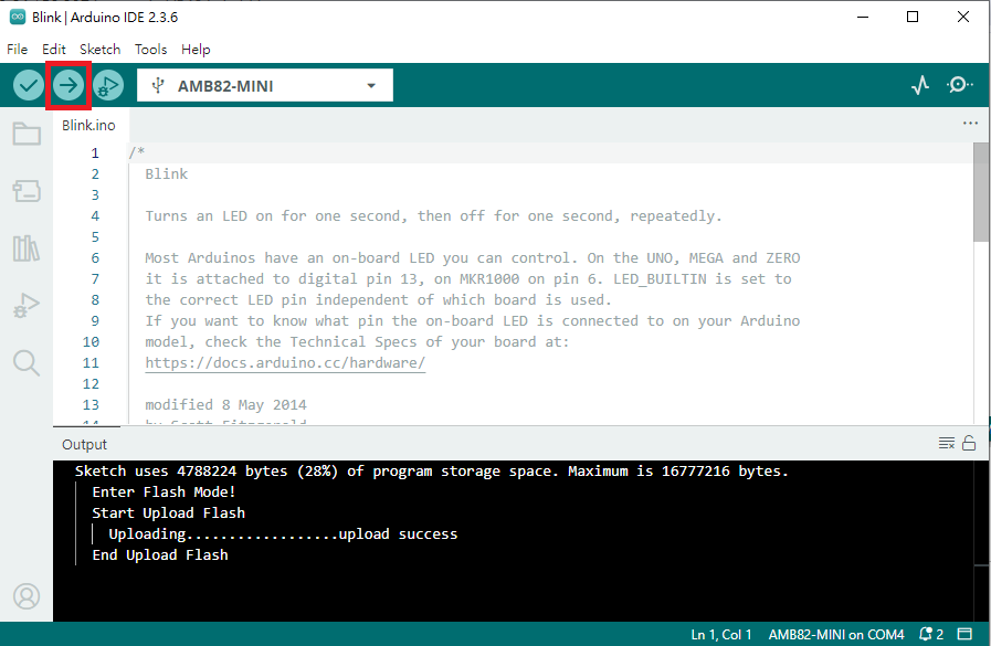
按下上傳按鈕。
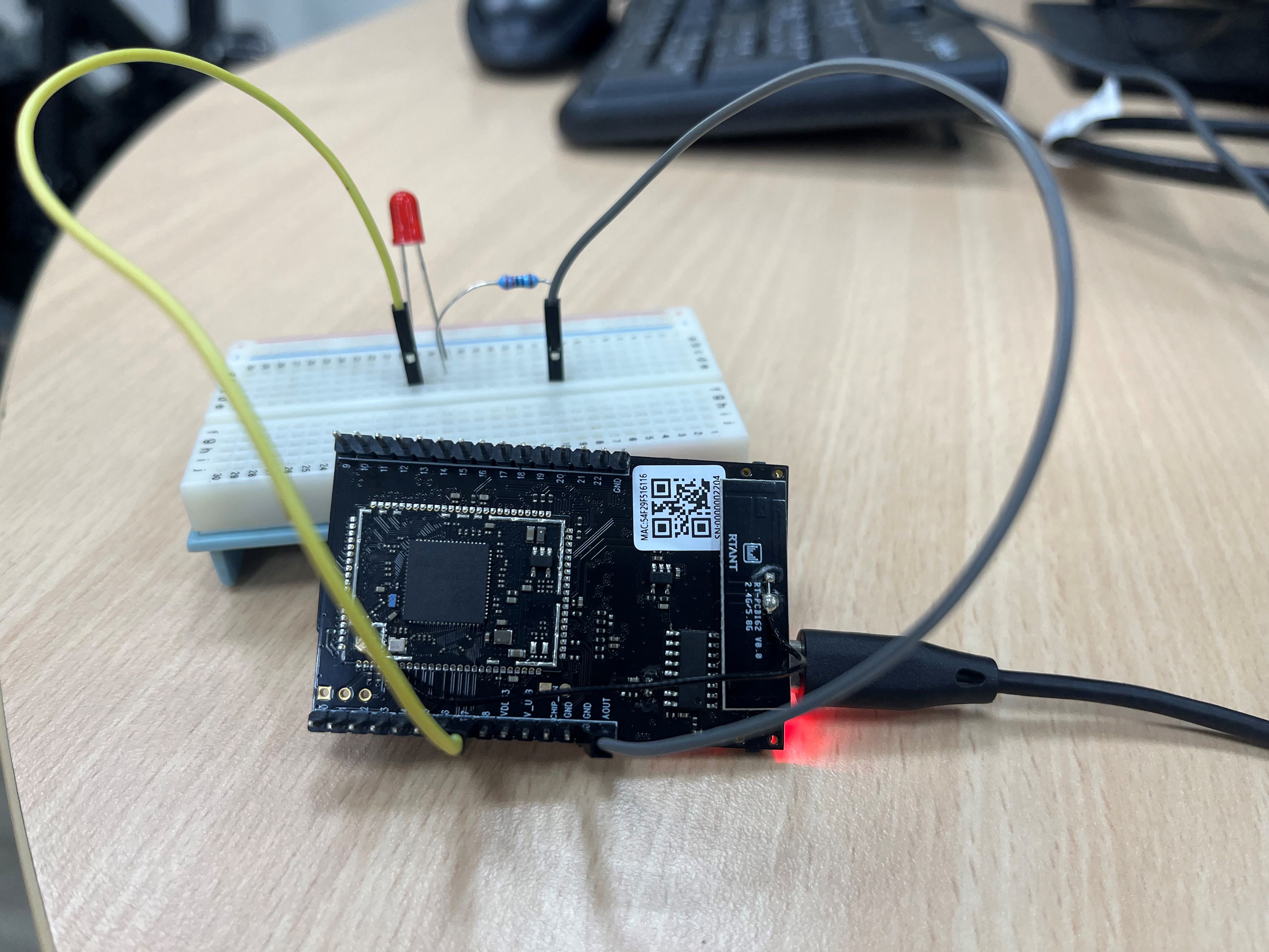
按下紅燈旁的按鈕讓程式執行。
-
外接LED閃燈
接線圖如下:
程式碼如下:
int led = 7; void setup() { pinMode(led, OUTPUT); } void loop() { digitalWrite(led, HIGH); delay(1000); digitalWrite(led, LOW); delay(1000); } -
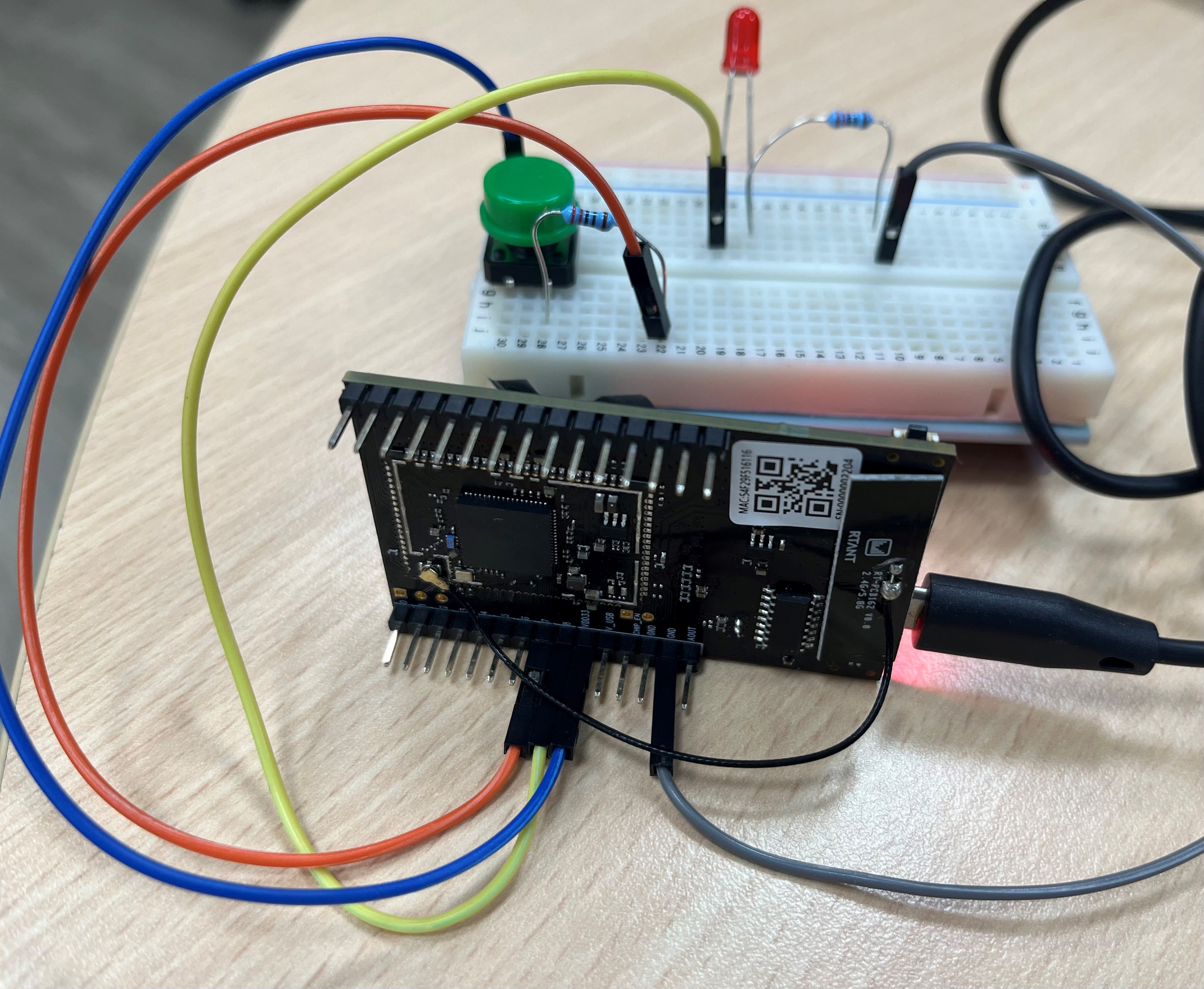
外接按鈕與LED
接線圖,如下。
程式碼,如下。
#define LED_PIN 8 #define BUTTON_PIN 7 void setup() { pinMode(LED_PIN, OUTPUT); pinMode(BUTTON_PIN, INPUT); } void loop() { if (digitalRead(BUTTON_PIN) == HIGH) { digitalWrite(LED_PIN, HIGH); } else { digitalWrite(LED_PIN, LOW); } } -
超音波測距
接線圖,如下。

程式碼,如下。
/*
 * Demonstrates use of HC-SR04 ultrasonic range module
 *
 * This sketch sends a 10us pulse HIGH at trigger pin of HC-SR04.
 * HC-SR04 return a pulse HIGH at echo pin which corresponds the distance.
 *     Time = Width of Echo pulse, in us (micro second)
 *     Distance in centimeters = Time / 58
 *
 * HC-SR04 works at 5V domain.
 * It means the echo pin needs level shift from 5V to 3.3V.
 * We can either use a level converter or use resister to divide the level.
 *
 Example guide:
 https://ameba-doc-arduino-sdk.readthedocs-hosted.com/en/latest/ameba_pro2/amb82-mini/Example_Guides/GPIO/Measure%20Distance%20HCSR04%20Ultrasonic.html
*/

const int trigger_pin = 12;
const int echo_pin = 11;

void setup()
{
    Serial.begin(115200);
    pinMode(trigger_pin, OUTPUT);
    pinMode(echo_pin, INPUT);
}

void loop()
{
    float duration, distance;

    // trigger a 10us HIGH pulse at trigger pin
    digitalWrite(trigger_pin, HIGH);
    delayMicroseconds(10);
    digitalWrite(trigger_pin, LOW);

    // measure time cost of pulse HIGH at echo pin
    duration = pulseIn(echo_pin, HIGH);

    // calculate the distance from duration
    distance = duration / 58;

    Serial.print(distance);
    Serial.println(" cm");

    // wait for next calculation
    delay(2000);
}
-
閃燈